

Line Driver Car Audio: What It Does and How to Choose

You've picked an amplifier, but behind the factory radio there's nowhere to plug in its RCA cables. You want stronger, cleaner sound, not a different dashboard or lost steering-wheel controls. A line driver car audio setup can help, but choosing one starts with understanding the signal your car produces, not buying the box with the highest advertised voltage.
Table of Contents
- What a Line Driver Does for a Factory Radio
- How Signal Flows From Speaker Wire to Amplifier
- Line Driver Compared With Other Ways to Feed an Amp
- Use Cases Where a Line Driver Changes the Result
- Selection Criteria for Gain, Channels, Noise and Impedance
- Wiring and Installation Steps That Prevent Noise
- Common Line Driver Problems and How to Fix Them
- Confirm Your Setup Before You Buy
What a Line Driver Does for a Factory Radio
Say you like your factory touchscreen and want to keep it. Your new amplifier needs a low-level audio signal, but the radio sends an amplified signal through speaker wires. Think of those wires as someone shouting across a room, while the amplifier's RCA input expects a normal conversation. An appropriate converter changes the message's level without intentionally changing its content.
There's an important naming distinction. A line-output converter, or LOC, converts speaker-level audio into line-level audio. Strictly speaking, a line driver boosts a line-level signal. Some powered integration products do both, which is why installers and product pages sometimes use the terms interchangeably. Always check what the device accepts, rather than trusting its name.
This factory-radio installation illustrates where conversion equipment fits.
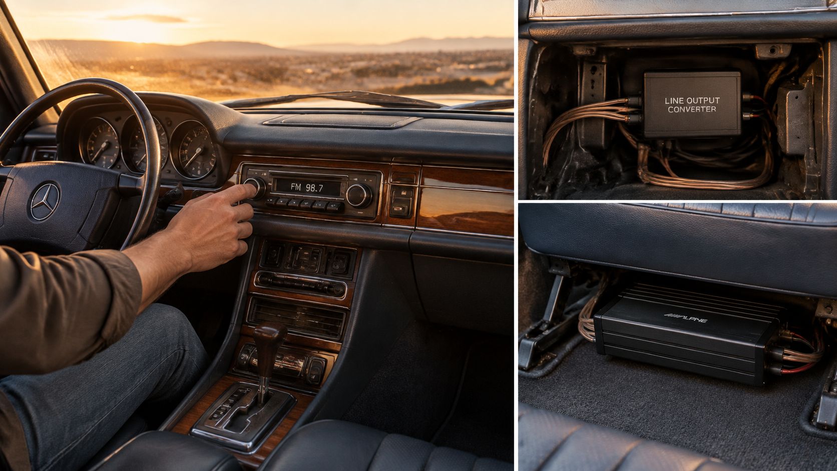
The job behind the dashboard
A suitable integration device must handle several tasks:
- Find usable audio. Take a signal from speaker outputs carrying the frequencies your new amplifier needs.
- Match signal levels. Convert that signal into something the receiving input can handle.
- Preserve factory operation. Avoid disrupting the original radio's expected electrical load or vehicle integration.
- Protect the next input. Keep the output below the amplifier's or processor's overload point.
Voltage explains why selection matters. Audio Intensity's installation guide describes typical passive factory speaker outputs around 2 to 4 Vrms, aftermarket preamp outputs around 2 to 6 Vrms, and factory-amplified speaker leads around 8 to 15 V. These are reference ranges, not guaranteed measurements for your vehicle.
The overlap doesn't mean speaker wires and RCA inputs are interchangeable. Circuit design, grounding, input impedance, and maximum accepted voltage also matter. Most aftermarket receivers already provide preamp connections, while factory radios often require another way to obtain the amplifier feed.
Before buying: Confirm whether the car has a factory amplifier. The dashboard radio alone doesn't tell you how strong the signal will be at your chosen connection point.
Keeping the original radio means you need a compatible integration path. That might be a separate LOC, a combined converter and line driver, or suitable high-level inputs built into another component.
How Signal Flows From Speaker Wire to Amplifier
For a factory-radio upgrade using a converter, the signal runs in one direction:
Head unit → speaker wires → converter or combined line driver → RCA cables → amplifier → speakers.
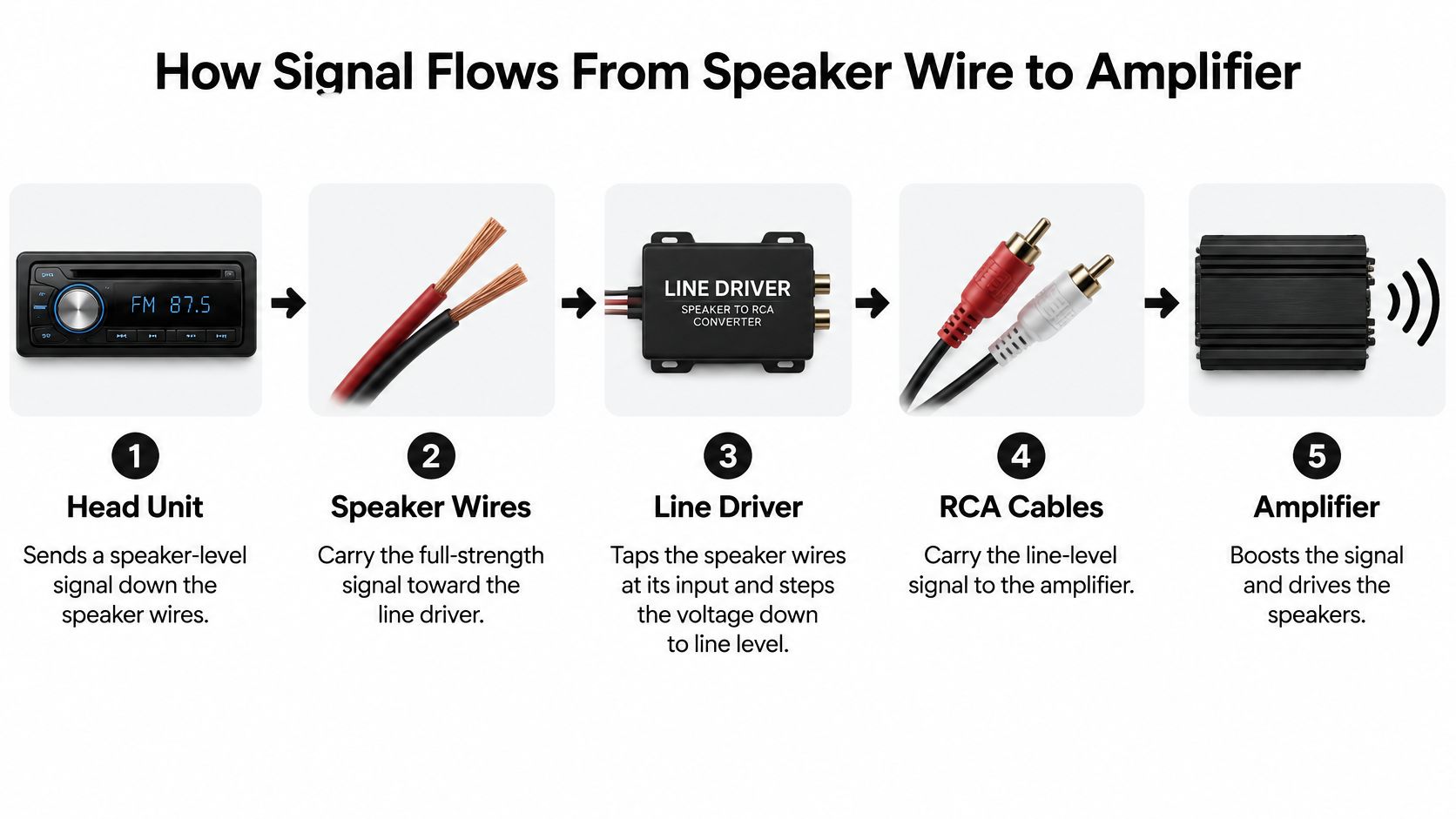
The radio's speaker output carries the audio waveform plus enough electrical power to move a speaker cone. The converter keeps the waveform and strips out that muscle, scaling the signal for an input built to process audio rather than drive a load. Your aftermarket amplifier then supplies the power the upgraded speakers need.
Consider a concrete mismatch. A factory lead measured at 9 V meets a crossover input that clips near 2 Vrms: the extra voltage adds distortion, not headroom, because the input overloads before the signal reaches anything that can use it. And while an RCA plug that fits the jack proves the connector mates physically, the voltage arriving through it still has to match what the circuit behind that jack accepts.
Typical signal levels by source and what the line driver must do
On the receiving side, the AudioControl Matrix owner's manual cautions that many crossovers and amplifiers clip near 2 Vrms, although equipment designed for higher input levels can accept more.
| Signal source | Typical level | How you confirm it | Line driver role |
|---|---|---|---|
| Passive factory speaker outputs | About 2 to 4 Vrms | Measure AC voltage across the speaker pair you plan to tap | Scale down to a line-level signal for the amp input |
| Aftermarket head-unit preamp outputs | About 2 to 6 Vrms | Check the radio's rated preamp output in its specifications | Usually not needed; the radio already supplies line level |
| Factory integrated amplifier at speaker leads | About 8 to 15 V | Measure AC voltage at the factory amplifier's speaker outputs | Use a higher-voltage-compatible unit with clipping protection |
| Receiving crossover or amplifier input | Often clips near 2 Vrms | Check the input's maximum accepted level in its manual | Output must stay below this threshold unless the receiver rates higher |
A worked example pulls this together. Say your meter reads 6 Vrms on the pair you intend to tap, and the amplifier input you are feeding clips near 2 Vrms. The conversion stage has to attenuate that signal to below 2 Vrms, roughly a third of the measured value, and you set that by watching the measurement rather than trusting the knob position.
Vrms describes the effective voltage of an alternating signal. Peak-voltage ratings use a different convention, so compare only specifications expressed the same way.
Once an input exceeds its clean operating range, it clips the waveform. You hear sharpness, congestion, or rough vocals instead of the improvement you expected, and lowering the amplifier's output afterward cannot undo distortion introduced upstream.
This video provides another view of the installation context.
Two checks decide which unit your car needs, and the speaker-lead voltage comes first. Measure the actual pair you intend to use, because a door-speaker output and a factory subwoofer output can carry different voltage and different frequency content. Voltage compatibility and useful musical content are separate requirements, and both must pass before the conversion stage can do its job.
Line Driver Compared With Other Ways to Feed an Amp
Does the original radio stay in the car? Start there. If it stays, something has to turn the radio's speaker-level output into a signal the amplifier can use cleanly. That job might belong to a separate converter, the amplifier itself, or a DSP.
The simplest suitable path usually creates fewer problems. Every added interface brings another box, another set of connections, and another gain adjustment that can introduce noise or throw off the system's level. Each component works like an adapter: it has to accept what the radio sends and deliver what the next device expects.
The main options differ by where the conversion work happens.
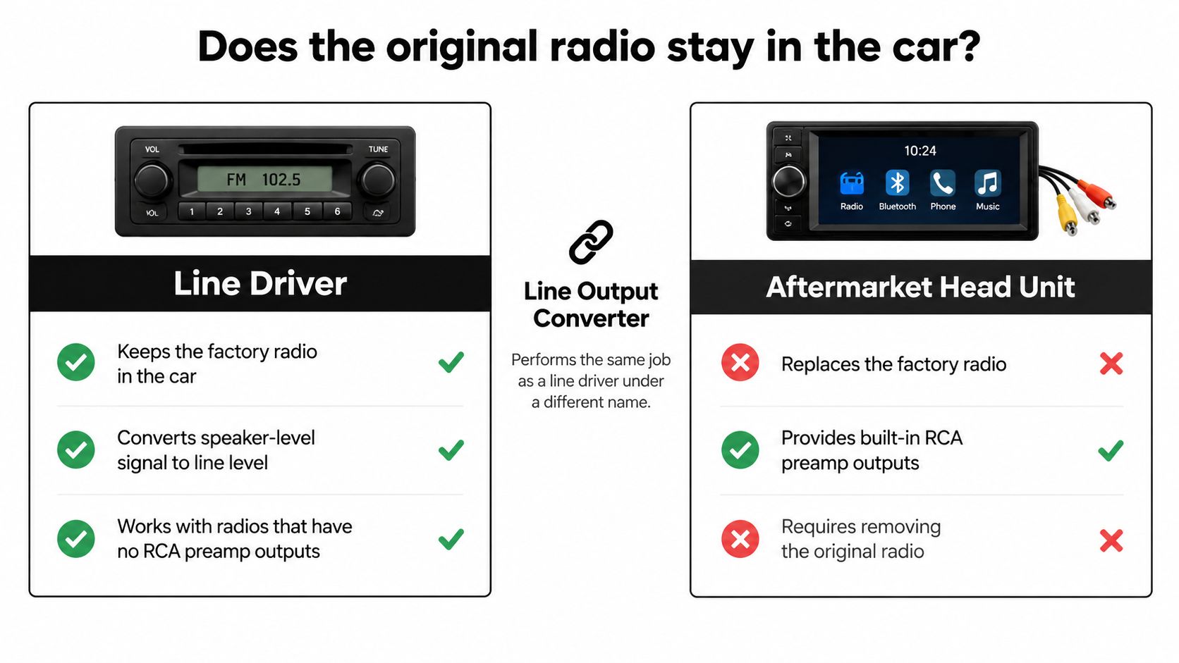
Line driver and alternatives compared on the same criteria
| Option | Suits which radio | Signal accepted | Main trade-off |
|---|---|---|---|
| Powered LOC or combined converter and line driver | Factory radio that stays in the car | Speaker-level wires when explicitly supported | Powered output adjustment, but adds a box, power connection, and gain setup |
| Passive line-output converter (LOC) | Factory radio that stays in the car | Speaker-level wires within its rating | Simple attenuation; output control depends on the radio and downstream gain |
| Preamp outputs on an aftermarket head unit | Aftermarket head unit | RCA line level at the downstream amplifier | Requires replacing the factory radio |
| Amplifier with high-level inputs | Factory radio, fewer boxes | Speaker-level wires within its rating | Integration and tuning features are limited to those built in |
| DSP with high-level inputs | Factory radio in a multi-amp system | Speaker-level wires within its rating | Added cost and setup work in exchange for processing control |
That first distinction matters in signal terms. A passive LOC mainly reduces voltage, while a powered converter can buffer the source and provide adjustable output. A line-level-only driver cannot accept speaker wiring by itself, so it belongs after conversion. The line-output converter guide provides additional context for that purchase.
Choose by the work the system needs
Suppose the measured speaker-lead signal stays clean and falls inside the amplifier's high-level input range. In that case, the amplifier can be the conversion point, and a separate converter may only duplicate a function the system already has.
If the amplifier cannot accept that signal, or you want accessible output adjustment, a powered LOC or combined converter and line driver gives you a dedicated control point. Judge an amplifier's high-level inputs by their voltage acceptance, load compatibility, and available controls rather than by where the connection sits on the chassis.
Replacing the radio with an aftermarket receiver that has suitable preamp outputs usually removes the need for speaker-level conversion. For a complex factory-amplified system, a high-level DSP may provide signal summing, equalization, and routing. Add a separate converter when the DSP's own inputs do not meet the vehicle's requirements.
Signal-path hardware comes before downstream product choices. An Aquatic AV BR-B65A Car Enclosure is an MDF enclosure with a carpeted finish; it may suit the speaker and amplifier package, but voltage acceptance still determines whether a converter belongs in the chain.
The useful verdict is straightforward: buy missing functions, not duplicate ones. Write down the radio's output form, the signal you measured, and the amplifier's input limits. If one component already bridges that gap, another box must earn its place through output adjustment, summing, equalization, or routing.
Use Cases Where a Line Driver Changes the Result
Factory-radio upgrades aren't an unusual corner of car audio. DataIntelo's car-audio market report estimates that OEM-installed systems represented 68.32% of worldwide market value in 2025. That market-value share isn't a count of vehicles, but it helps explain why equipment designed around original radios remains relevant.
The installation decision still belongs to the individual car. Consider these hypothetical setups, where the installer measures the signal before selecting hardware.
A sedan getting amplified door speakers
The owner wants better front and rear sound without changing the dashboard. The installer confirms that the radio directly drives the original speakers and measures a clean, lower-level speaker output at the intended listening volume.
A compatible converter feeds the new multichannel amplifier. The important result isn't merely that RCA sockets now exist. The installer has established a usable input signal while retaining the original user interface and checking that warning sounds remain appropriate.
A premium vehicle with factory amplification
Here, the installer finds a separate amplifier and a stronger output at the speaker leads. Some channels carry only a restricted frequency band, so tapping the most convenient wire could leave the new system without part of the music.
This setup needs adequate speaker-level input capacity, plus any necessary channel summing or vehicle-specific integration. An adapter intended only for modest radio outputs may overload. The badge on the grille doesn't select the converter; the measured output and circuit requirements do.
A truck or SUV adding a subwoofer
The owner wants more bass while leaving the door speakers alone. The installer measures a candidate speaker pair and checks whether useful bass remains present as the radio volume changes.
A suitable converter can supply the subwoofer amplifier, but only if that source contains the bass the system needs. Otherwise, the installer must choose another pickup point or use appropriate integration processing.
Choose equipment for the signal at the connection point, not for the vehicle's price tier.
A replacement receiver with compatible preamp outputs presents the counter-case: connect those outputs directly to the amplifier unless another function is needed. For a retained factory radio, lower-level speaker outputs may suit a basic converter, while stronger amplified outputs demand greater input capacity. Measure first, then confirm the rating.
Selection Criteria for Gain, Channels, Noise and Impedance
An adjustable output control is the first specification to compare, ahead of the maximum voltage printed on the box. A line driver is a gain-staging tool: its job is to hand the next device a clean signal at the level that device expects, and a wide adjustment range is what makes that matching possible. Treat the input ceiling and the output capability as two separate ratings. A converter can accept a strong speaker-level signal on the way in yet still need its output dialed down for a sensitive amplifier input.
A high output rating represents available headroom. The correct setting is the clean level your receiving amplifier or DSP needs, and the practical sequence in this amplifier gain-setting guide helps distinguish matching sensitivity from merely turning everything up.
Line driver selection criteria with the spec to check and the red flag
Use this checklist when comparing product manuals. The numerical examples describe specific models rather than universal minimums.
| Criterion | What to check | Why it matters | Red flag |
|---|---|---|---|
| Gain and output voltage | Adjustable output matched to the receiving input rating | Establishes usable sensitivity without overloading the next device | Fixed high output that exceeds the receiving input's range |
| Input impedance | High-impedance input and any required selectable load settings | Supports the factory output's expected electrical conditions | A fixed setting that doesn't suit the vehicle |
| Channel count | Enough independent paths for the planned front, rear, and subwoofer feeds | Preserves required routing and controls | Missing independent channels the system needs |
| Noise and distortion | Published distortion, frequency response, and test conditions | Helps assess whether the converter can pass a clean signal | No meaningful performance specifications |
| Speaker-level power handling | Maximum input voltage or power rating under stated conditions | Prevents overloading the converter's input | Rating missing or below the measured factory output |
| Output impedance | Published output impedance and cable guidance | Helps assess compatibility with downstream inputs and cable capacitance | No specification when planning demanding cable runs |
Understand what the specifications tell you
A converter input rated around 20 kΩ draws far less current than the 4-ohm load a speaker presents, so input impedance and speaker impedance measure different things. Some converters add a selectable lower-impedance load because certain factory amplifiers expect a speaker-like load before they deliver full output. Engage that setting when the vehicle guidance calls for it; a number that merely looks close to a speaker rating is the wrong reason.
Draw the signal paths on paper before ordering. Say the system keeps factory fader action: the front speaker pair feeds one converter channel pair, the rear pair feeds a second pair, and the subwoofer amplifier takes a third feed. A four-channel amplifier then still receives independent front and rear information. A two-channel unit suits a sub-only tap, while splitting one stereo feed across every amplifier input abandons the separation the extra channels exist to preserve.
Read noise and distortion figures against their stated test conditions, because a spec sheet that omits the test level or bandwidth tells you little. A stronger clean signal works like raising your voice in a noisy room: the room stays just as loud, yet your words stand further above it. A healthy converter output lets you run the amplifier's input sensitivity lower, pushing any hiss contributed at that stage further below the music. Noise already present in the factory source travels through unchanged.
Specification check: Compare ratings under their stated conditions. Input power handling, maximum output voltage, and amplifier power are different specifications.
Speaker-level power handling describes what the converter can tolerate at its input terminals, while the wattage the new amplifier delivers comes from that amplifier's own rating. Low output impedance helps a converter drive a longer cable cleanly, though routing, shielding, and the receiving input still share the job.
Separate a true incompatibility from a shopping preference. A fixed input impedance serves well in a vehicle whose factory output is comfortable with it, and an unpublished spec means you should confirm the value before trusting that unit in a demanding install. The voltage present at your factory speaker leads is the number that decides which input rating you need.
Wiring and Installation Steps That Prevent Noise
Plan the connection points before removing trim. The AudioControl LC6i user manual documents a six-channel converter with 20 kΩ input impedance, 9.5 Vrms maximum output, and speaker-level handling up to 400 W at 4 ohms. Those are equipment-specific limits, not universal targets.
Use the checklist image as a quick wiring reminder, then verify the details for your vehicle.
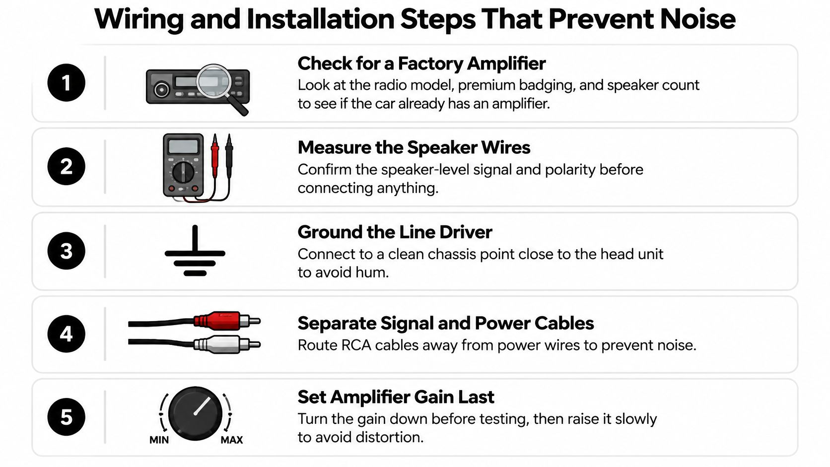
Make the connections in a controlled order
- Identify the factory system. Check vehicle documentation, amplifier location, and wiring diagrams. Premium badges and speaker count are clues, not proof of a particular circuit.
- Measure the intended speaker pair. Use an AC-capable true-RMS meter and a suitable test signal for repeatable readings. Measure across the pair, not from either speaker conductor to chassis. Music is useful for listening checks but gives a changing voltage reading.
- Verify the input and load requirements. Confirm the converter supports the factory output topology and voltage. Never join speaker negatives together or ground them unless the wiring instructions explicitly permit it.
- Check vehicle integration. Determine whether the installation affects factory amplifier communication, warning sounds, steering-wheel controls, or display functions. Follow vehicle-specific shutdown and battery-disconnection procedures before making permanent connections.
- Evaluate the factory tuning. Listen and measure at different volume settings for bass reduction or changing equalization. Choose an appropriate pickup point or restoration strategy; ordinary EQ can't recover information that's absent.
- Mount and ground securely. Place powered equipment in a dry, protected location with access to its controls. Use the manufacturer's grounding instructions and a secure chassis connection where specified.
- Separate signal and power wiring. Route RCA cables away from high-current and ignition wiring where practical. Protect cables at metal openings and use the amplifier wiring diagram guide to plan power, signal, and turn-on connections.
- Set gain and verify operation. Begin with conservative settings, establish the source's maximum clean level, then adjust converter output within the receiving input's rating. Set amplifier gain separately, using an oscilloscope or distortion-aware method when available.
A meter reports voltage; it doesn't prove the waveform is unclipped. If distortion appears, locate the first stage producing it rather than repeatedly adjusting the final amplifier.
Finish with an engine-running noise check in a safely ventilated location. Test startup, shutdown, calls, navigation prompts, and factory alerts so the installation works beyond music playback.
Common Line Driver Problems and How to Fix Them
Distortion at higher volume is a reason to stop increasing gain. Start with a familiar recording and reduce the converter output. If the roughness disappears, investigate the receiving input's sensitivity and the converter's own clipping indicators.
If it remains, check the signal entering the converter. A distorted factory output stays distorted after conversion, even when every downstream adjustment is conservative. The useful diagnostic habit is to find where clean audio first becomes damaged.
Line driver symptoms, likely causes and fixes
| Symptom | Likely cause | Fix |
|---|---|---|
| Distortion or harshness at high volume | Excess gain or clipping at a signal stage | Lower gain, check with a known track, and verify clean levels with suitable test equipment |
| Hiss or alternator whine | Ground-reference problem, source noise, or interference near signal cables | Inspect grounds and temporarily reroute RCA cables away from power |
| No sound from the amplifier | Incorrect input selection, connection error, or missing turn-on signal | Check input mode, speaker-pair wiring, power, and remote turn-on |
| Weak or missing bass | Factory roll-off, restricted source bandwidth, cancellation, or crossover settings | Check source content and polarity before adjusting crossover or EQ |
| Steering-wheel or display controls not working | Disturbed wiring or missing vehicle integration | Restore connections and confirm interface compatibility with an installer |
| Amp shuts down or goes into protection | Speaker short, unsuitable load, supply problem, or overheated equipment | Stop playback and inspect power, ground, speaker wiring, and equipment ratings |
Separate noise, cancellation, and missing audio
Alternator whine changes with engine speed; steady hiss behaves differently. Note whether the noise changes with radio volume, amplifier gain, or engine operation. That observation helps distinguish upstream noise from interference or noise introduced later.
For no sound, verify amplifier power and turn-on status before changing gain. Reversed polarity on a single speaker pair usually doesn't mute the amplifier, but inconsistent polarity between combined channels can cause cancellation. Check positive and negative identification rather than swapping wires at random.
Weak bass needs the same discipline. Temporarily disable an unintended high-pass filter and confirm that the selected factory output contains low-frequency information. Boosting EQ before diagnosing cancellation or missing source content can waste headroom without solving the problem.
Turn the system off before inspecting shorts. Repeatedly forcing an amplifier out of protection isn't a repair.
A converter input overload primarily causes signal distortion; it isn't the default explanation for an amplifier entering protection. Treat protection as a separate power, load, thermal, or equipment fault until testing establishes otherwise.
Input-switch checks, accessible connection inspections, and conservative gain adjustments may be straightforward. Network faults, unknown factory wiring, load-sensing behavior, or persistent protection events deserve an installer with vehicle-specific information and proper test equipment.
Confirm Your Setup Before You Buy
Collect the following details in a single note before speaking with a retailer or installer. Photos of equipment labels and the intended mounting area can prevent an unnecessary return.
- Vehicle identity. Year, make, model, trim, and factory audio package.
- Original equipment. Radio model, factory amplifier presence, and any interface already installed.
- Speaker layout. Speaker locations, sizes, and which components will stay connected.
- Upgrade plan. Amplifier channels, subwoofer plans, and whether a DSP is included.
- Electrical requirements. Measured speaker-lead output, converter input capacity, and the receiving amplifier's input sensitivity rating.
That last line does the heavy lifting. The measured speaker-lead voltage tells you how much signal the factory radio delivers, and the amplifier's input sensitivity rating tells you how much signal it needs to reach full power. When the converter's adjustable output sits comfortably between those two figures, the amplifier gain stays low and the noise floor stays down.
Also ask who will check factory alerts, turn-on behavior, and clean gain settings after installation. Fold those checks into the installation plan so they happen before the trim goes back on, while the wiring is still easy to reach.
Audio Jam Inc in Bear, Delaware, offers speaker-lead voltage measurement, line-driver selection, gain setup, and factory-integration checks. Visit Audio Jam Inc to book a local appointment or shop parts online, and bring your vehicle details and amplifier specifications so the team can match the interface to your system.