

Ground Wire Installation: A Practical Car Audio Guide

You've finished the wiring, turned the gain down, and expected clean bass. Instead, the amplifier cycles into protect mode, the lights flicker with the beat, or a high-pitched whine follows engine speed. The first suspect is often the RCA cable, but a poor ground wire installation causes many of these failures before the signal path deserves blame.
A car audio ground isn't just a short cable attached to the nearest bolt. It's the amplifier's return path to battery negative, and every weak connection adds resistance to that path. Paint, rust, loose hardware, undersized copper, and excessive cable length can turn a promising installation into an unstable one.
The reliable approach treats grounding as a resistance-and-surface-prep problem. Choose the conductor, select the chassis point, route the cable safely, terminate it properly, and verify the result with a meter. The target isn't a neat-looking ring terminal. It's a low-resistance connection that stays stable while the vehicle vibrates, heats, cools, and gets wet.
Table of Contents
- What a Good Car Audio Ground Does
- Choosing the Right Ground Wire Gauge and Length
- Finding and Prepping the Grounding Point
- Routing the Ground Wire Through the Chassis
- Crimping Versus Soldering the Ground Terminal
- Testing Resistance and Confirming a Solid Ground
- Common Ground Wire Myths and Troubleshooting Noise
What a Good Car Audio Ground Does
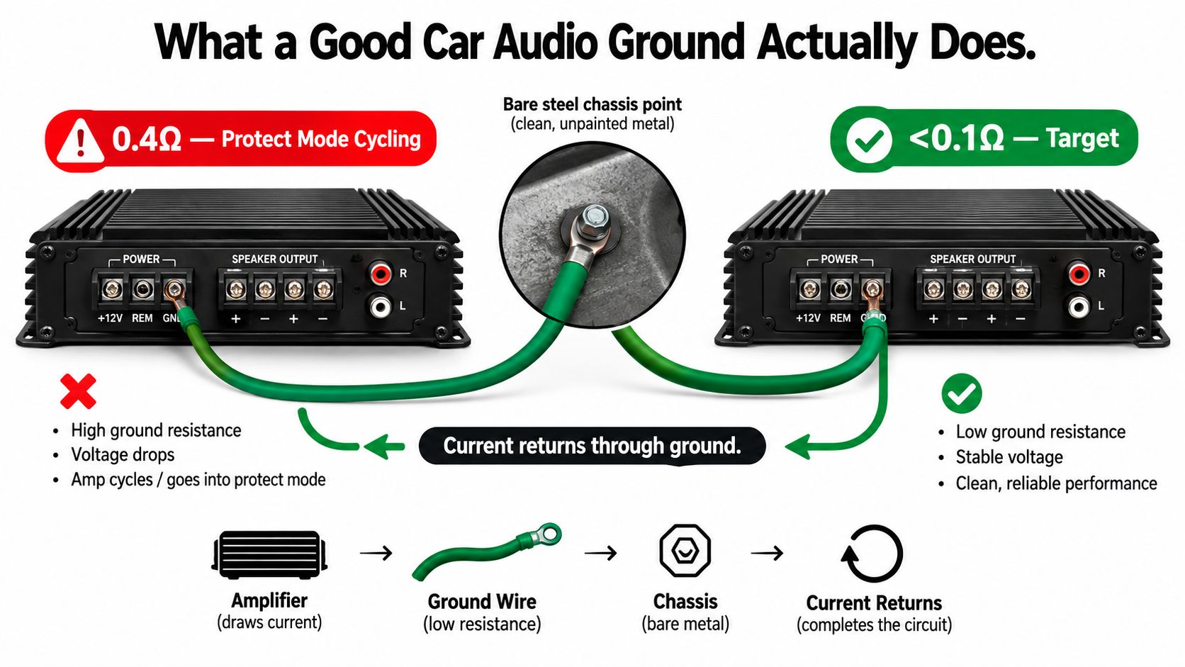
An amplifier that reads 0.4 ohms from its ground terminal to battery negative may look connected, but that result is already above the practical target of under 0.1 ohm described in automotive grounding guidance from Watson's StreetWorks. Under load, that extra resistance can cause voltage loss, protect-mode cycling, reduced output, or audible noise.
The ground cable carries the amplifier's return current toward battery negative. Resistance anywhere along that route creates voltage drop, leaving the amplifier with less usable voltage when its power supply is working hardest. A short cable on a small, dirty contact patch can perform worse than a longer cable secured to clean, solid chassis steel.
Make four decisions before tightening anything
- Choose the wire. Match the conductor to amplifier demand and cable length. Copper provides a more dependable current path than copper-clad aluminum, especially in higher-current systems.
- Choose the point. Select bare, structurally sound chassis metal close to the amplifier. A factory ground bus or seat-bolt bracket may work, but confirm that it is not shared with sensitive vehicle electronics. For multiple amplifiers, a single nearby distribution point keeps return paths controlled. Separate chassis points can work when each is clean, secure, and measured, but they may introduce different ground potentials.
- Route the cable. Keep it short and protect it from sharp edges. Avoid hinges, moving trim, water exposure, and unnecessary proximity to signal wiring.
- Terminate the connection. Use a correctly sized ring terminal. Remove paint and rust from the contact area, clamp the terminal firmly, and protect the finished joint from oxidation.
Practical rule: A competent ground should measure less than 0.1 ohm end-to-end, from the amplifier terminal to battery negative, after installation. The reading should come through clean metal and a sound terminal, not paint, rust, or loose hardware.
That measurement gives the installation a useful diagnostic yardstick. If the number is high, changing amplifier settings will not repair the ground.
Choosing the Right Ground Wire Gauge and Length
Wire gauge should follow the amplifier's real current demand and the distance between the amplifier and chassis point. The positive cable and ground cable form one power circuit, so resistance on either side matters. Matching the ground to the positive lead is reasonable for a very short run, but a longer return path deserves more copper rather than a convenient assumption.
For runs under 18 inches, matching the positive wire gauge is generally acceptable in car audio practice. As the ground extends toward 36 inches or beyond, stepping up the ground conductor can reduce return-path loss. The table below is a practical starting framework, not a substitute for the amplifier manufacturer's wiring requirements.
| Amp RMS Wattage | Under 18 inches | 18 to 36 inches | Over 36 inches |
|---|---|---|---|
| Under 500 watts | 8 AWG | 8 AWG, consider 4 AWG for demanding systems | 4 AWG |
| 500 to 1,000 watts | 4 AWG | 4 AWG | 1/0 AWG when current demand and installation length justify it |
| 1,500 watts and up | 1/0 AWG | 1/0 AWG | 1/0 AWG or larger system-specific conductor |
The wattage categories in this guide are practical installation ranges, not universal electrical limits. RMS output, amplifier efficiency, impedance, charging-system condition, and music demand all affect current draw. A compact class-D amplifier may need less input current than an inefficient amplifier producing similar rated output.
Copper quality matters
For systems pushing past 1,000 watts, pure oxygen-free copper is the safer choice over CCA, particularly when the ground run is long or the vehicle sees moisture. Don't mix a high-quality OFC positive feed with a substantially less capable CCA ground and assume the larger printed size cancels the difference.
The chassis itself becomes part of the return path after the ground terminal. That means the cable gauge is only one part of the circuit. A heavy conductor attached to thin, painted, or corroded metal still creates a weak connection.
Keep the ground as short as practical, but don't sacrifice a proper contact patch for a shorter route. A clean point a little farther away is better than a nearby bolt buried in coating.
Finding and Prepping the Grounding Point
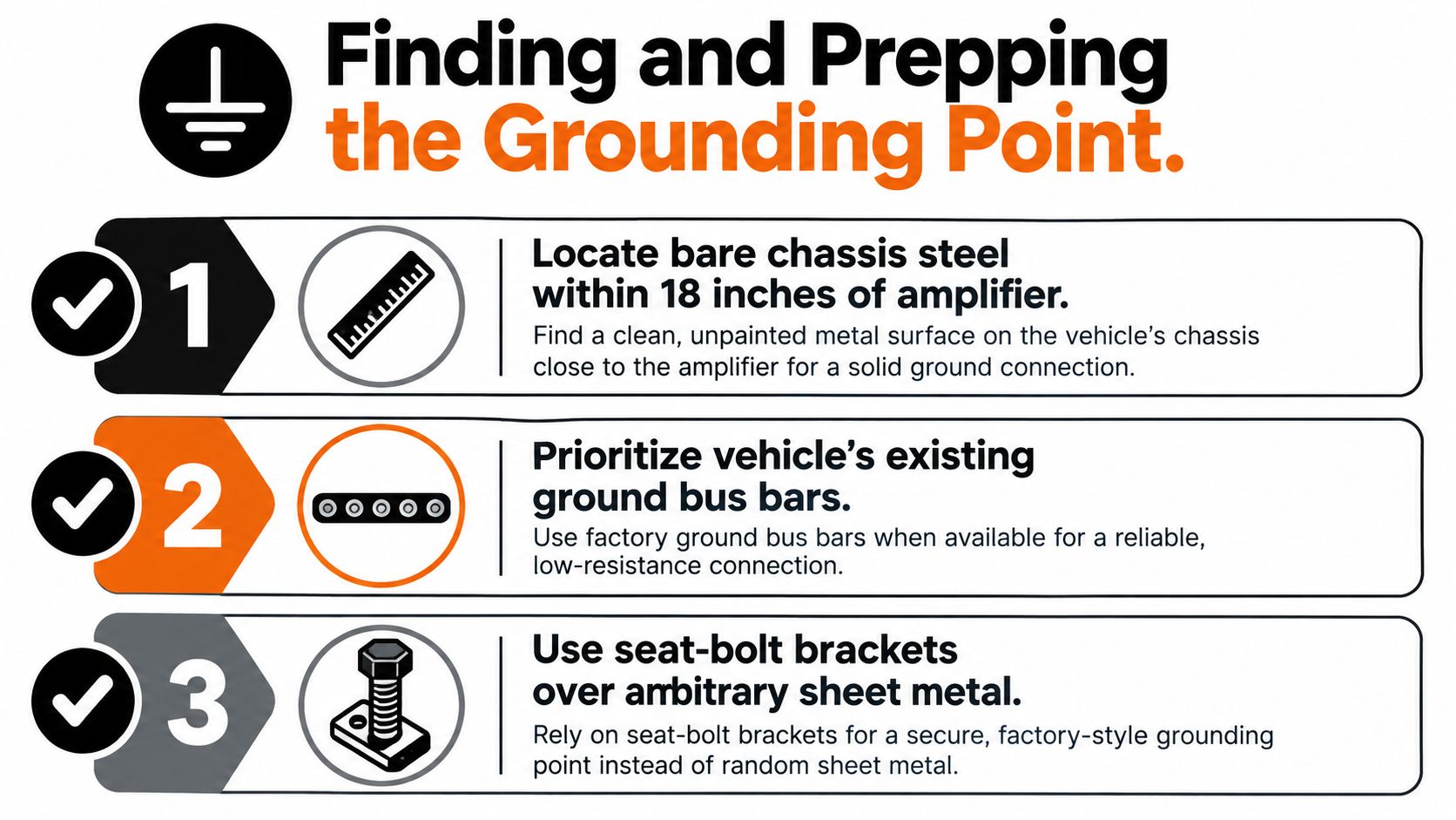
Start by looking for solid chassis steel within 18 inches of the amplifier. Existing ground bus bars and suitable seat-bolt brackets deserve attention before you drill into random sheet metal, because established mounting points may provide stronger mechanical support and a more dependable connection.
Don't assume every factory bolt is electrically useful. Some fasteners pass through painted brackets, coated floor panels, or assemblies isolated from the chassis. Others may already carry return current for the ECU, airbag module, instrument cluster, sensors, or lighting. A large amplifier can disturb those shared reference points and introduce noise or fault symptoms.
Prepare the metal, not just the hardware
Remove paint, rust, undercoating, and residue with a rotary tool or an 80-grit abrasive disc. Expose a clean bare-metal area extending at least one inch beyond the terminal ring in every direction, so the ring sits fully against conductive steel rather than against a remaining edge of coating.
If no suitable factory fastener exists, drill a pilot hole in a structurally sound area. Check both sides before drilling for fuel lines, brake lines, wiring, airbag components, and other hidden equipment. Deburr the hole, then protect nearby exposed metal with zinc-rich primer or self-etching paint. Keep the actual terminal contact patch bare, and seal the surrounding cut without coating between the ring and chassis.
A star washer can help bite through light surface contamination, but it can't replace proper preparation. Put it under the terminal where it can maintain mechanical pressure, use a corrosion-resistant bolt and nut where appropriate, and tighten the connection firmly without distorting thin sheet metal.
Before final assembly, test continuity from the intended grounding point to a known-good chassis reference. After bolting down the ring, test the complete path again. If the reading changes substantially, the fastener or contact surface is doing more work than the cable.
Routing the Ground Wire Through the Chassis
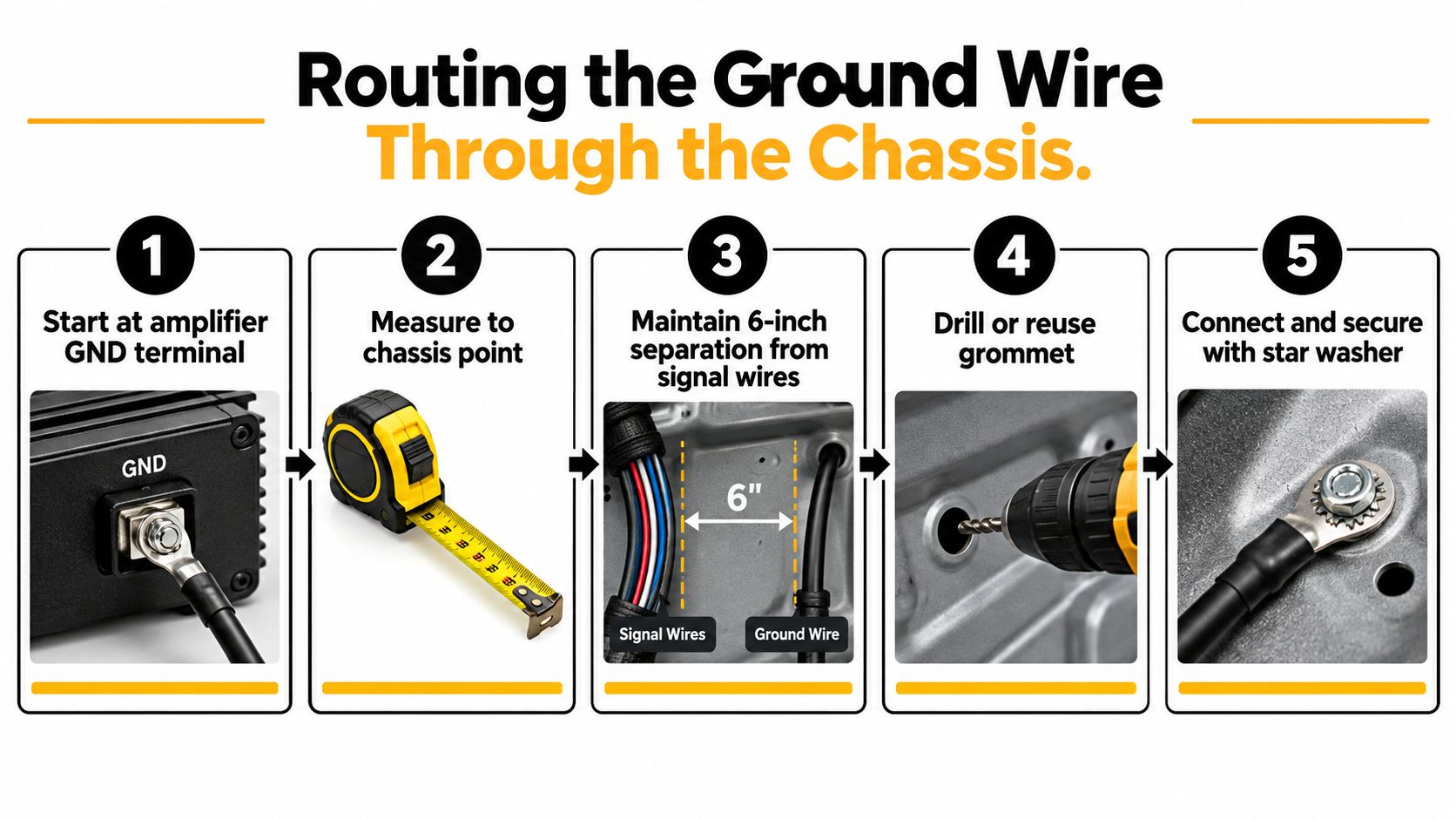
A ground cable usually doesn't need a complicated route. It needs a protected route that doesn't rub, pinch, or run alongside sensitive signal wiring for long distances. Start at the amplifier's GND terminal, measure the cleanest path to the selected chassis point, and cut only enough cable to allow a relaxed connection.
Keep the ground at least 6 inches from RCA cables, speaker leads, and factory sensor harnesses where practical. Running the ground on the opposite side of the vehicle from the power cable can also reduce large shared loop areas, although the quality of the chassis connection remains more important than blindly following a side-of-vehicle rule.
Protect every transition
If the cable passes through a firewall or metal panel, reuse a factory pass-through whenever possible. When drilling is unavoidable, use a properly sized rubber grommet or silicone-protected boot. Bare cable against a drilled edge is a delayed short circuit, not a finished installation.
Secure the run with plastic P-clips or adhesive cable mounts every 8 to 12 inches, and add strain relief within 4 inches of the terminal. Leave roughly a finger's width of slack at the amplifier end so vibration doesn't pull directly on the terminal. Don't leave a heavy cable hanging from the amp connection.
Run your hand along the planned route before installing the cable:
- Sharp edges: Cover or rework any metal edge that can cut insulation.
- Hinges and pedals: Keep the cable away from door hinges, seat tracks, pedals, and moving brackets.
- Heat and fluids: Avoid exhaust components, heater boxes, fuel lines, brake lines, and areas that collect water.
- Service access: Leave enough room to remove trim and inspect the connection later.
The ground doesn't need to look dramatic. It needs to remain mechanically quiet and electrically consistent.
Crimping Versus Soldering the Ground Terminal
Both crimping and soldering can produce a sound ground terminal. The failure usually comes from using the wrong terminal, applying insufficient heat, creating a cold joint, or leaving the connection unprotected from moisture and movement.
For a road-going daily driver, a properly executed crimp is usually the most repeatable option. Use a ring terminal matched to the cable gauge and a quality hex or ratcheting crimper that compresses the barrel evenly. A full-thickness crimp should pass a firm tug test without the conductor sliding from the terminal.
| Factor | Crimp | Solder |
|---|---|---|
| Speed | Fast once the correct tool is available | Slower, especially on large cable |
| Vibration tolerance | Strong when properly compressed and supported | Good only with sound technique and strain relief |
| Tools | Hex or ratcheting crimper, correct terminal | High-wattage iron or propane torch, solder, terminal |
| Main failure | Loose or undersized crimp | Cold joint, overheated insulation, solder wicking |
| Best fit | Road-going vehicles and serviceable installs | Bench-built enclosures or fixed marine work |
| Required protection | Adhesive-lined heat-shrink and protected contact | Adhesive-lined heat-shrink and protected contact |
What a reliable crimp looks like
Strip only the length required by the terminal barrel. Insert all strands, crimp the correct section, and tug the cable aggressively enough to expose a weak joint before the vehicle does. Cover the barrel with adhesive-lined heat-shrink, shrinking it evenly until it seals around the insulation.
Apply dielectric grease around the finished chassis connection where moisture is a concern. Grease doesn't make a bad electrical interface good, so apply it after the metal surfaces have been prepared and the terminal is seated properly.
Soldering has a place. A high-wattage iron or propane torch can heat a large terminal quickly, and rosin-core solder can fill a correctly prepared joint. But solder wicks up the conductor and can create a stiff transition that concentrates vibration stress if the cable isn't supported.
A soldered ground isn't automatically superior. A clean, properly compressed crimp with heat-shrink is often more durable in a vehicle than a poorly heated solder joint.
For marine, off-road, and other high-moisture installations, corrosion protection and strain relief are essential regardless of termination method. A perfect joint still fails if water reaches exposed copper.
Testing Resistance and Confirming a Solid Ground
Test the installation before reconnecting the amplifier to power. A multimeter cannot predict performance at full load, but it can reveal a loose terminal, contaminated contact surface, or poor return path before those faults become harder to trace.
Disconnect the amplifier, set the meter to ohms, and touch the probes together first. This shows the resistance in the test leads and gives you a baseline. Measure from the amplifier ground terminal to a clean, known-good chassis point, then repeat the test from the amplifier terminal to battery negative. Press the probes firmly against bare metal. Paint, anodizing, and corrosion will produce a misleading result.
| Reading | Status | Action |
|---|---|---|
| Under 0.1 ohm | Excellent | Keep the connection and proceed to load testing |
| 0.1 to 0.5 ohm | Acceptable for most amplifiers | Inspect the terminal, cable length, and contact surface if symptoms appear |
| 0.5 to 1.0 ohm | Marginal | Rebuild the connection and look for voltage drop at operating volume |
| Over 1.0 ohm | Unacceptable | Relocate or rebuild the ground before powering the system |
Use under 0.1 ohm as the working target for a strong connection. Readings above 0.5 ohm deserve investigation, especially in a high-current amplifier installation. A low static reading does not replace a load test, because the meter applies very little current.
Test under real current
Play a 40 Hz sine wave at moderate volume, then measure voltage between battery negative and the amplifier ground terminal. Aim for less than 0.2 volts during the test. Stop immediately if the ground cable, terminal, or amplifier becomes unusually hot.
If the system produces noise, temporarily using a ground-loop isolator on the RCA path can help identify whether the signal wiring is involved. Treat the isolator as a diagnostic tool, not a repair. It will not correct a weak chassis bond or a high-resistance ground.
Retest after the vehicle has been driven for a month. Vibration and thermal cycling can loosen hardware, shift trim, or expose corrosion that was hidden on installation day. A ground that passes an initial meter check still needs a secure fastener, protected metal contact, and stable cable support.
Common Ground Wire Myths and Troubleshooting Noise
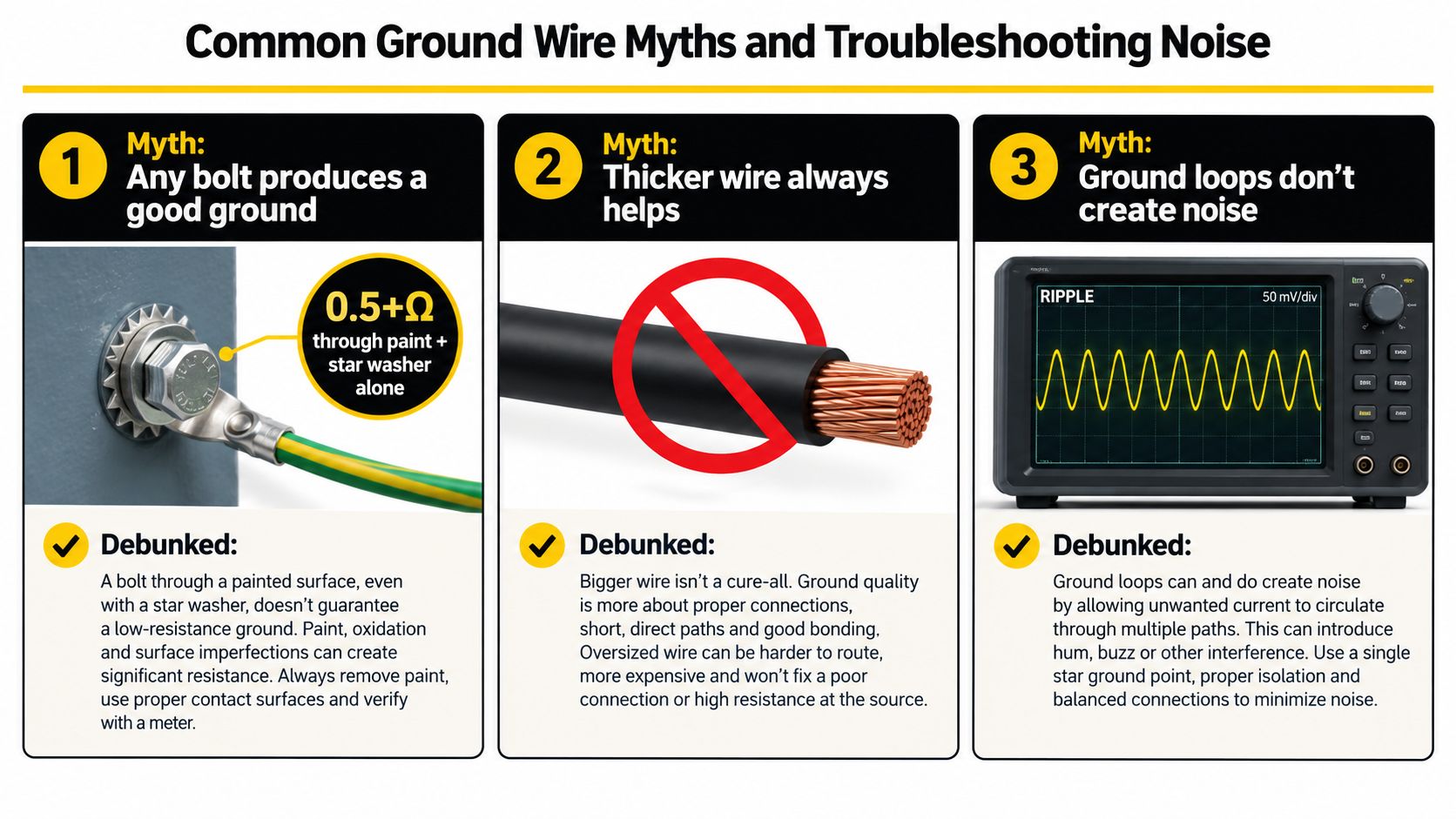
The nearest bolt isn't automatically a ground. Paint, powder coating, rust, and poor clamping can push the connection beyond 0.5 ohm, while a star washer by itself can't compensate for an insulated contact surface. The amplifier may still turn on, which makes this failure easy to misdiagnose.
Ground length matters too. Each additional foot of 4 AWG cable adds roughly 0.001 ohm in the example used by the grounding guidance from WireSolved, but the more important practical issue can be the total return-path quality and the loop area exposed to ignition and control-system noise. Keep the run short, but don't choose a bad point solely because it saves a few inches.
Factory ground points aren't always suitable either. A stock connection may share current with sensors, headlights, or ECU circuits. Adding an amplifier to that location can raise the local ground reference and place noise beside circuits that were never intended to carry amplifier return current.
Use the symptom to narrow the fault
- RPM-related whine: Check the ground connection and possible ground-loop path before replacing RCA cables. Engine-speed tracking points toward an electrical reference problem.
- Popping over bumps: Inspect the ring terminal, fastener, crimp, and any solder joint for movement or cracking. A connection that changes with vibration isn't finished.
- Hiss at high volume with the engine off: Check for ground-induced ripple and voltage loss at the chassis bond, then verify the signal gain structure.
- Protect-mode cycling: Measure the ground under load, inspect cable gauge and terminal temperature, and rebuild any connection that fails the resistance test.
A useful isolation test is a temporary 4 AWG jumper from battery negative directly to the amplifier ground terminal. Keep the jumper safely positioned and insulated from accidental contact. If the noise or instability disappears, you've isolated the vehicle's original ground route from the rest of the system and can focus on the chassis point, cable, or termination.
The fastest diagnosis is usually measurement. Don't replace signal cables until the ground passes both a resistance check and a loaded voltage-drop check.
Ground wire installation is small in physical scale but central to amplifier reliability. If you'd rather have the cable selection, chassis preparation, and testing handled together, Audio Jam Inc offers car audio installation and sells amplifiers, wiring, and accessories through its Bear showroom and online store. Visit Audio Jam Inc to review installation options or arrange help with a clean, test-verified system.