

Installing a Line Output Converter: A Practical Guide

You've kept the factory radio because it works well with the steering-wheel controls, vehicle chimes, and original dash. But the stock system runs out of authority when you turn it up, and replacing the entire infotainment unit would create more problems than it solves. You want an aftermarket amplifier or subwoofer, yet the vehicle offers speaker wires instead of the RCA preamp outputs that amplifier expects.
That's where a line output converter, or LOC, earns its place. It takes the high-level signal traveling to the factory speakers and converts it into a usable RCA preamp-level signal for an aftermarket amplifier. The difficult part isn't the splice itself. It's identifying where the signal comes from, understanding what the factory amplifier is doing to it, and keeping the vehicle's speaker-monitoring and turn-on logic satisfied.
Table of Contents
- Why You Might Need a Line Output Converter in the First Place
- Picking the Right LOC and Gathering What You Need
- Locating the Right Signal Source and Planning Mounting
- Wiring the Converter Step by Step
- Setting Gain and Testing the Signal
- Common Problems and What They Actually Mean
- When an LOC Is Not the Right Answer
Why You Might Need a Line Output Converter in the First Place
A factory radio may feed the speakers with an amplified, speaker-level signal, while an aftermarket amplifier expects a low-level RCA signal. Connecting those outputs directly can overload the amplifier's input stage, create distortion, or damage equipment. A line output converter, or LOC, reduces the factory signal to a usable level and passes it to the aftermarket amplifier through RCA outputs, as explained in this line output converter installation guide.
The practical reason to use one is often vehicle integration. A driver may want stronger bass or cleaner output while keeping the factory display, navigation, steering-wheel controls, and warning sounds. Replacing the radio is not required when the system provides a suitable speaker-level signal. The LOC taps that signal, converts it, and feeds the added amplifier.
Practical rule: Treat the LOC as an integration device, not a sound-quality upgrade. It preserves a usable signal path, but it does not automatically remove factory equalization, time alignment, filtering, or other processing.
The vehicle architecture decides the tap point
Some vehicles send speaker power directly from the radio. Others route it through a separate factory amplifier behind trim, under a seat, or in a luggage-area panel. Premium systems may filter and process each channel before it reaches the speakers. The vehicle may also monitor speaker loads and mute or report a fault when the electrical behavior changes.
The easiest wire to reach is not always the correct signal source. First identify whether the tap belongs at the OEM radio output or after the factory amplifier. The LOC should sit in the usable signal path before the aftermarket amplifier, with its input rating matched to the output at that location. The Metra LOC installation documentation describes supported connections to speaker outputs or OEM amplifier outputs rated up to 75 watts per channel.
Speaker-load behavior matters during diagnosis. If disconnecting a factory speaker causes the radio to mute, lose a channel, or set a fault, the system is monitoring that load. A converter or load-simulation feature may be needed rather than a simple splice.
Modern LOCs also accommodate higher-output factory radios and bridge-tied-load, or BTL, signals. BTL outputs do not behave like ordinary grounded speaker circuits. Using a converter designed for that signal type helps avoid wiring errors when the factory system is integrated with an older or lower-cost aftermarket amplifier. The line output converter technical guide explains the BTL conversion use case and the electrical difference involved.
Picking the Right LOC and Gathering What You Need
Choose the LOC after examining the vehicle's audio architecture, not by picking the cheapest unit on the shelf. A passive LOC suits a straightforward factory radio with moderate, clean speaker-level output. An active LOC is the safer choice when the factory signal is strong, the converter must sense audio, or you need a more dependable remote turn-on output.
Check the specifications against the exact tap point. Confirm the input rating, compatibility with floating or BTL outputs, load-simulation capability, and the behavior of the remote output with the vehicle's electronics. The InCarTec installation instructions describe a multi-channel converter accepting up to 80 watts per channel on the input side, with power, ground, and remote-turn-on connections. Compare that rating with the factory amplifier output you will connect, rather than the radio's advertised system power.
Passive versus active designs
| Feature | Passive LOC | Active LOC |
|---|---|---|
| Power requirement | Usually signal-powered | Requires power and ground |
| Typical use | Simple factory systems and moderate signal levels | Higher-output or more complex factory systems |
| Turn-on behavior | May require a separate remote source | Often includes signal sensing or remote output |
| Adjustability | Limited | Usually provides more control over output level |
| Load handling | May need additional load simulation | More likely to support factory-system integration features |
| Installation trade-off | Simpler wiring | More wiring, but greater control |
A passive unit keeps the install simple, but it can leave you solving turn-on or factory-load problems separately. An active unit adds power and ground wiring, yet usually gives more control when the vehicle monitors speaker behavior or shuts down an output after a load change.
Collect the parts before removing trim: the LOC harness, RCA cables, speaker wire or twisted signal leads, a reliable ground terminal, wire strippers, crimpers, a multimeter, loom, and fasteners. Heat-shrink and solder can improve protection, while a correctly sized crimp made with the proper tool is also suitable.
Keep power and remote wires away from the RCA route to reduce the chance of induced noise. For a powered converter, follow its wiring instructions. The cited guidance specifies 16 to 14 AWG power and ground wiring for example powered LOC installations. The aftermarket amplifier may need larger cable according to its current demand and cable length.
Locating the Right Signal Source and Planning Mounting
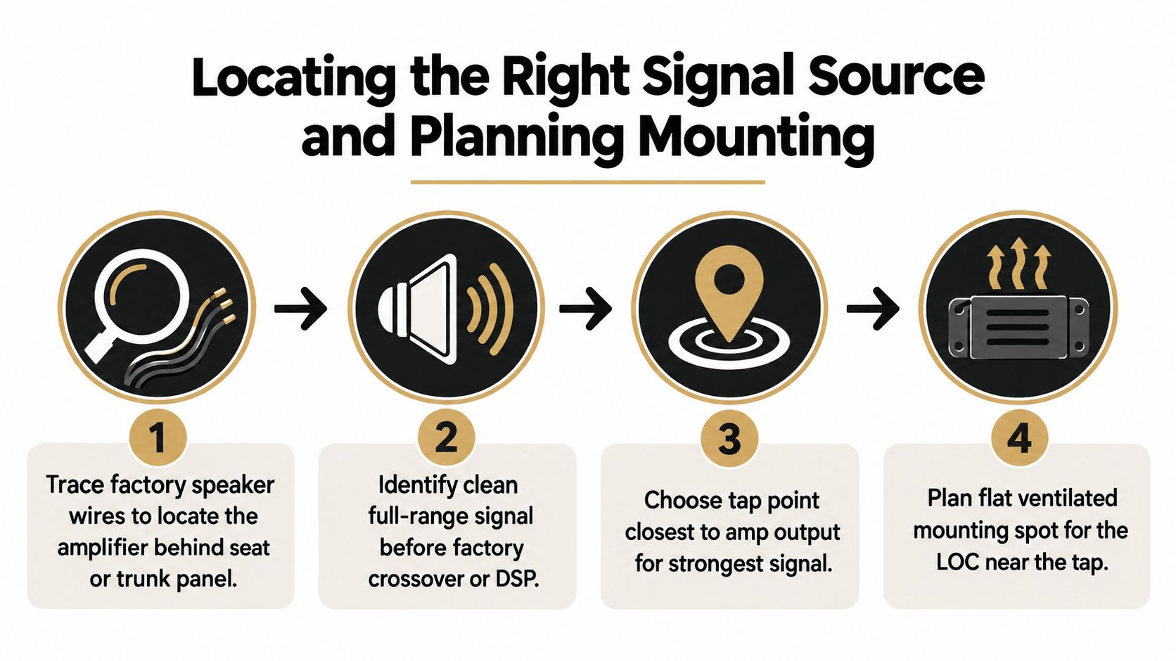
Before cutting anything, determine whether the vehicle has a separate factory amplifier. Trace the speaker wiring if you can access it, inspect the vehicle-specific wiring diagram, or identify the amplifier through the manufacturer's audio-system documentation. In premium systems, tapping the factory amplifier's speaker outputs is often cleaner than reaching behind the radio, but only if those outputs contain the frequency range you need.
A door speaker wire may carry a filtered signal intended only for a midrange or tweeter. A subwoofer tap may contain heavy bass processing and little usable midrange. The cleanest source is usually the appropriate full-range output before the factory crossover or DSP divides the signal, but the exact location depends on the vehicle's architecture.
Use a wiring check or continuity test to confirm the speaker pair and polarity. A battery pop test can help identify speaker movement on an isolated speaker circuit, but don't use it carelessly on connected vehicle electronics. Floating BTL outputs and factory amplifier circuits require more caution than a simple aftermarket speaker circuit.
Plan the physical layout before wiring
Mount the converter near the signal source when practical, but leave room to service it. Behind the dash can work for a compact unit. A trunk or side-panel location may be better when the factory amplifier and aftermarket amplifier are both in the rear.
Choose a dry, ventilated, vibration-safe location. Don't let the module hang from its harness, rest against a heater duct, or sit where trim movement can pinch the wires. Secure it to a stable bracket or surface, then plan the RCA route so it stays away from high-current power cables and sharp metal edges.
Keep channel pairs together and mark them before you make the first connection. Left and right polarity errors are easy to create when several factory wires use similar colors, and a wiring mistake at the signal source can produce a weak or hollow sound that looks like an amplifier problem.
Wiring the Converter Step by Step
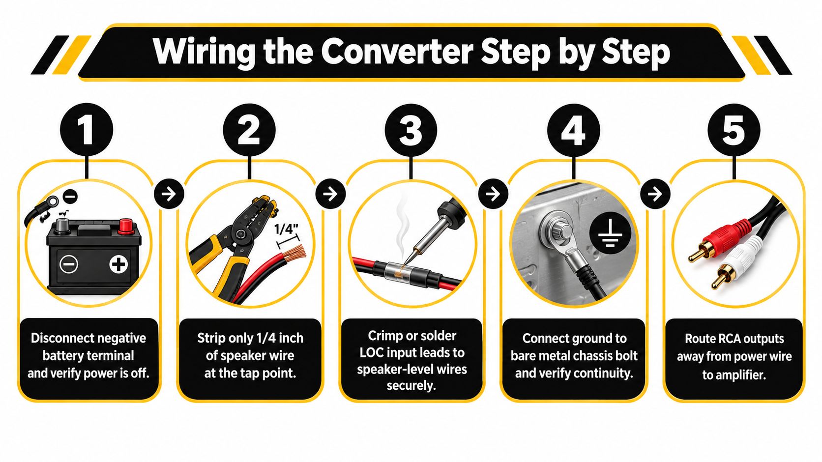
Disconnect the negative battery terminal before opening the harness. This protects the vehicle and reduces the chance of shorting a power conductor against the chassis, but remember that some vehicles require a specific shutdown procedure before battery disconnection. Keep the radio code, window initialization, and other vehicle-specific requirements in mind.
At the selected tap point, identify the positive and negative wires for each channel. Don't assume a wire color is correct because it matches a diagram from another trim level. Verify the pair with a wiring diagram, continuity check, or careful signal tracing. The basic technical sequence is to identify the speaker pair, confirm polarity, connect the LOC inputs, route its RCA outputs to the amplifier, and provide the required power, ground, and remote connections, as outlined in this step-by-step LOC wiring guidance.
Make the signal connections cleanly
Strip only enough insulation to make a secure connection. Keep the stripped section short, match every channel's polarity, and avoid leaving loose strands that can contact adjacent conductors. Crimp connectors firmly or solder and seal the joint with heat-shrink. Don't overtighten screw terminals, since that can damage the conductor or terminal block.
Connect the LOC RCA outputs to the amplifier with the channels identified. Route the RCA cable away from the amplifier's main power cable and other high-current wiring. If both must cross, crossing them at a right angle is generally preferable to running them together for a long distance.
Ground, remote, and power
A powered LOC needs a solid chassis ground. Choose clean, unpainted metal, remove surface coating where necessary, and fasten the terminal securely. Manufacturer guidance emphasizes a clean metal ground point, while the referenced installation guide identifies 16 to 14 AWG wiring for example powered LOC power and ground connections.
The remote-turn-on lead determines when the amplifier wakes up. Use a switched source that becomes active with the radio, a compatible blue antenna or remote trigger where appropriate, or the LOC's signal-sensing output if the model provides one. A converter can be fully powered and still fail to wake the amplifier if its remote signal never changes state.
Provide dedicated fused power to an active converter when its instructions require it. Keep the fuse close to the power source, protect every pass-through with a grommet, and never treat the LOC's power lead as a substitute for the amplifier's dedicated power circuit.
Use the following video as a visual reference for the general wiring sequence, then follow the instructions for your specific converter and vehicle.
Setting Gain and Testing the Signal
Gain isn't a volume knob. It matches the signal voltage coming from the LOC to the input sensitivity of the amplifier. Turning it up to make the system louder can push either the converter or amplifier into clipping, and reducing the gain later may not remove distortion that was created upstream.
Start with the LOC output adjustment low and the amplifier gain low. Set the factory radio to a consistent listening level, then play a familiar reference track or a suitable test tone. Increase the amplifier gain gradually while monitoring the output with a multimeter or listening carefully for the first clear signs of clipping. Back it down once the signal is no longer clean.
Use the amplifier specification as the reference
A multimeter can measure AC voltage at the amplifier's speaker outputs, but the correct target depends on the amplifier's rated power, speaker impedance, and test frequency. Don't use a made-up universal voltage target. Use the amplifier's documented output specification and calculate the expected voltage from its rated power and the connected load.
| Amplifier sensitivity | Target AC voltage for 4 Ω | Clip threshold |
|---|---|---|
| Low input sensitivity | Use the amplifier's rated power and load calculation | The first measurable or audible clipping |
| Medium input sensitivity | Use the manufacturer's specified output at the connected load | Stop at clean output, then reduce slightly |
| High input sensitivity | Keep the LOC and amplifier gains conservative | Any harshness, waveform flattening, or audible breakup |
After setting the amplifier, adjust the LOC output only as needed to provide a healthy signal without overdriving the amplifier input. Confirm left and right channel assignment with a known recording. If bass sounds thin or hollow, check polarity at the LOC inputs and amplifier speaker outputs before changing equalization.
Test the RCA outputs for unwanted DC offset and investigate any abnormal reading instead of connecting expensive equipment and hoping for the best. Confirm the amplifier turns on and off cleanly, stays on at normal listening levels, and doesn't introduce noise when the engine starts. Reinstall trim only after the system passes those checks.
Common Problems and What They Actually Mean
A working splice doesn't prove that the integration is correct. Factory audio systems can mute, sleep, alter their output, or report a speaker fault when the electrical load no longer looks familiar. AudioControl's support guidance explains that some factory systems need resistors placed across speaker positive and negative outputs so the vehicle continues to detect the expected speaker presence, especially when the tapped circuit is sensitive to load monitoring. Review its support guidance for a powered LOC with no audio before adding resistors, and use only values approved for the vehicle and interface.
Read the symptom before replacing parts
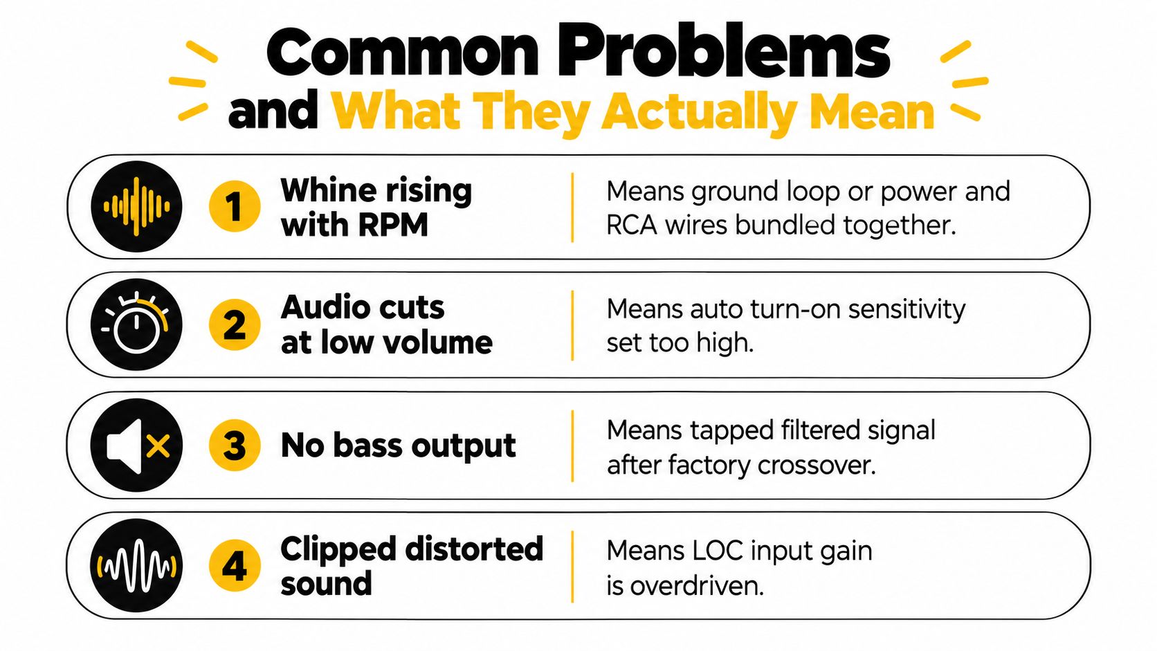
- Whine that follows engine speed: Check the LOC and amplifier grounds first, then separate RCA cables from power wiring. A new converter won't cure a poor ground path.
- Audio that disappears at low volume: The factory amplifier may be entering a sleep state, or the LOC's signal-sensing threshold may be wrong. Try the correct signal-sense setting or a compatible integration interface.
- Turn-off popping: Inspect the remote-turn-on timing and grounding. A delay module or controlled remote source may be necessary.
- Distortion that remains after gain reduction: The factory source may already be clipping, or the tap may carry processed audio that the LOC can't cleanly accept. Move the tap point or use a converter designed for that output.
- No bass from an otherwise active system: You may have tapped a filtered channel or reversed polarity on one side. Check the source content before blaming the subwoofer amplifier.
A converter that becomes unusually hot during ordinary operation deserves attention. Recheck its input rating, wiring, ventilation, and load compatibility. If electrical operation is stable but the sound remains uneven, the factory EQ curve, time alignment, crossover behavior, or speaker phase may be responsible. In that situation, a DSP or more advanced integration module can solve a problem that another LOC cannot.
When an LOC Is Not the Right Answer
An LOC is a sensible bridge when the factory system provides a usable speaker-level signal and the vehicle doesn't require deeper integration. It becomes the wrong tool when the source is heavily processed, the factory amplifier expects a specific speaker load, or the vehicle's audio network controls turn-on and output behavior.
A premium factory system may distribute different equalized signals to different speakers. Tapping one channel and sending it to a subwoofer amplifier can work, but it may also carry a narrow frequency range or aggressive bass management. A summing interface or DSP can combine channels and correct the response without abandoning factory features.
A vehicle with speaker-load diagnostics presents a different problem. A passive converter may complete the signal path electrically, yet the factory system can mute the channel because the added connection doesn't resemble the original speaker load. In that case, use a vehicle-specific load-generating interface or an active converter designed for the system instead of adding random resistors.
| Scenario | Best method | Why |
|---|---|---|
| Simple factory radio with usable speaker outputs | LOC | Provides RCA output without replacing the radio |
| Factory amplifier with heavy EQ or time alignment | DSP or advanced integration module | Corrects or combines processed channels |
| Speaker-load diagnostics cause muting | Vehicle-specific integration interface | Preserves the expected electrical behavior |
| Factory radio already has RCA pre-outs | Direct RCA connection | Avoids unnecessary signal conversion |
| Complete head-unit replacement | New radio's pre-outs | Uses the aftermarket source directly |
| Factory chimes and controls must remain active | OEM integration module or compatible DSP | Preserves vehicle functions while adding amplification |
Before purchasing, answer three questions. Do you know whether the signal comes from the radio or a factory amplifier? Do you need to preserve chimes, steering-wheel controls, and volume compensation? Are you trying to add modest amplification, or do you want accurate system tuning?
Audio Jam Inc offers car-audio installation support and sells integration products such as the AudioControl The Epicenter Micro Bass Restoration Processor and Line Output Converter for connecting aftermarket equipment to factory radios. If the wiring source, load behavior, or remote turn-on remains uncertain, visit Audio Jam Inc to discuss the vehicle before cutting into the factory harness.